

Common Fiber Laser Cutting Problems and Solutions in Production
Introduction
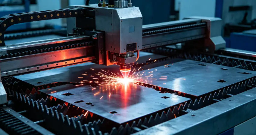
In real sheet metal factories, fiber laser cutting problems rarely appear as sudden machine failures or system alarms.
Instead, they develop gradually during production. Operators usually first notice subtle changes–such as a slight increase in burr formation, unstable edge equality after material switching, or incomplete cuts appearing intermittently in a batch.
These signals often look minor, but they are early indicators of process imbalance.
In most cases, cutting instability is not caused by a single machine fault. It is the result of small deviations accumulating across gas delivery, optical condition, focus position, and process parameters.
This guide summarizes real production cases and explains how these issues typically develop–and how experienced operators restore stable cutting performance step by step.
I. Common Fiber Laser Cutting Problems in Production
1. When Cutting Edges Start to Become Rough or Burr Appears

In daily production, edge quality issues rarely appear suddenly. A machine that was running perfectly in the morning may still look stable in the afternoon, with normal motion, consistent sparks, and no alarm signals.
The problem is usually discovered only when operators inspect finished parts and notice that the bottom edge has become slightly rough. At first, it may only occur on one side of the sheet or in certain geometries, making it easy to overlook.
Over time, however, burr formation becomes more consistent, indicating that the cutting process has gradually lost balance.
What is actually happening in the cutting zone?
Inside the kerf, molten metal must be fully ejected by assist gas. When this balance is disturbed, molten material begins to reattach to the bottom edge, forming burrs.
This typically happens when multiple small factors overlap:
- Assist gas pressure becomes slightly unstable during cutting
- Nozzle condition begins to degrade or becomes partially contaminated
- Focus position shifts subtly after material or program changes
- Cutting speed is pushed too close to the process limit for efficiency
None of these factors alone may cause immediate failure–but together, they gradually reduce cutting stability.
How experienced operators usually recover stability
Instead of adjusting parameters randomly, the first step in real factories is always to re-stabilize the system:
They start by confirming that gas pressure remains consistent throughout the cut, not just at idle. Then they inspect the nozzle for carbon buildup or deformation, followed by checking whether focus offset has drifted after recent production changes.
Only after these variables are confirmed stable will cutting speed be adjusted again, gradually, based on test cuts rather than full-sheet production.
In most real cases, burr issues are resolved not by “one parameter fix,” but by restoring system balance.
2. When the Machine Cuts, But the Material Is Not Fully Penetrated

Another common situation in production is when the machine appears to be working normally. The cutting head moves smoothly, sparks look even, and there are no alarms.
However, after parts are removed from the sheet, operators discover that some sections are still attached or only partially cut through.
At first glance, the cut line may look almost complete, but certain areas remain unseparated.
This type of issue is especially frustrating because it does not interrupt the machine–it only appears at the end of the process.
What is really happening?
Although laser power at the source may be sufficient, the energy reaching the bottom of the material is reduced during transmission or interaction with the process zone.
In real production environments, this usually comes from:
One of the most common causes is contamination on the protective lens. Even a thin layer of dust or residue can scatter the beam and significantly reduce penetration capability, especially on thicker materials.
Another frequent cause is incorrect focus position after switching material thickness. A setting that works for thin sheet may leave the focal point too high for thicker plates, resulting in incomplete penetration at the bottom.
Cutting speed also plays a critical role. When speed is not reduced for thicker materials, the laser simply does not have enough interaction time to fully penetrate the sheet.
How recovery is typically done on the shop floor
Experienced operators usually start from the optical system. The protective lens is checked first and replaced if any contamination is visible.
Next, focus position is recalibrated using a reference material instead of relying on previous job settings.
Finally, cutting speed is reduced slightly for validation cuts before returning to full production.
In most cases, penetration problems are resolved once energy delivery and focus alignment are restored.
3. When Slag Appears on Only Side of the Cut

In stable production, cutting edges should be consistent across the entire sheet. However, operators sometimes notice an unusual pattern: one side of the part remains clean, while the other side shows heavy slag accumulation.
This asymmetry is a strong diagnostic signal because it usually indicates airflow imbalance rather than laser power instability.
What is happening inside the kerf?
Molten material is not being ejected evenly. Instead of flowing out symmetrically, it is pushed toward one side of the cut, where it solidifies as slag.
This is rarely caused by a single parameter.
In many cases, nozzle alignment is slightly off-center, causing uneven gas distribution. Even a small deviation can significantly change airflow behavior at high cutting speeds.
In other situations, the compressed air or nitrogen supply contains moisture or contamination, leading to unstable gas flow during cutting.
Incorrect gas selection or pressure settings can also contribute, especially when switching between materials like stainless steel and mild steel.
How factories correct this issue
The first step is always mechanical alignment. The nozzle center position is rechecked to ensure proper symmetry.
Next, the gas system is inspected. Water separators are drained, and gas purity and pressure stability are verified.
Finally, a side-by-side test cut is performed to confirm whether the airflow has returned to balance.
Once gas distribution becomes stable again, asymmetrical slag typically disappears.
4. When Piercing Becomes Unstable or Delayed

Piercing issues usually appear at the very beginning of the cutting process. The laser fires normally, but instead of a clean entry, the piercing time becomes longer, and the entry point may appear enlarged or burned.
Although the rest of the cut may still look normal, unstable piercing often indicates that initial energy delivery is not properly synchronized.
What causes this instability?
In thick plate processing, piercing requires a carefully controlled combination of peak power, gas timing, and focal position.
If peak power is insufficient, the material does not fully melt during the initial pulse. If gas delay timing is incorrect, molten material is not expelled at the right moment, leading to irregular entry holes.
When step or progressive piercing is not enabled for thicker materials, the system attempts to pierce in a single step, which often results in instability.
How operators stabilize piercing performance
In production, piercing issues are usually solved by adjusting the sequence rather than a single parameter.
Operators may increase peak power for thick materials, enable step piercing mode, and adjust gas delay timing to ensure proper melt ejection.
Once the piercing process becomes stable, the rest of the cutting cycle usually returns to normal automatically.
5. When Lens Contamination Becomes a Recurring Problem

In some workshops, operators notice that protective lenses need frequent cleaning or replacement. Cutting quality may suddenly drop, even if all parameters remain unchanged.
This is often one of the most overlooked issues in daily production.
What is actually causing the damage?
In many cases, the root cause is not the lens itself, but the environment around it.
Poor gas purity allows moisture or oil particles to reach the optical path. Incorrect nozzle height can expose the lens to more spatter and reflection. Cutting reflective materials such as aluminum or copper increases back reflection risk. Dust accumulation in the workshop further accelerates contamination.
When contamination becomes severe, operators typically need to inspect or replace the protective lens. A step-by-step replacement guide can be found here: How to Replace a Protective Lens in a Laser Cutting Machine
How production teams prevent recurrence
Instead of only cleaning lenses more frequently, stable factories focus on upstream control:
They ensure gas is properly dried and filtered, maintain correct nozzle distance, and apply protective strategies when processing reflective materials.
A structured cleaning and inspection schedule is also implemented to prevent gradual degradation.
II. Why Most Cutting Problems Are Not Machine Failures
Across real production environments, more than 80% of fiber laser cutting issues are not caused by hardware failure.
They are caused by:
- Gradual parameter drift during production changes
- Consumable wear such as nozzles and lenses
- Instability in assist gas systems
- Manual adjustments without baseline reference
In other words, most problems are process-related rather than equipment-related.
III. How to Troubleshoot Fiber Laser Cutting Issues Step by Step
A stable troubleshooting workflow in production usually follows this order:
1. Check assist gas system stability
2. Inspect optical components (lens and nozzle)
3. Verify focus position calibration
4. Review cutting speed and process parameters
5. Perform controlled test cuts before batch production
Systematic diagnosis is more effective than random parameter adjustment.
IV. Preventive Maintenance for Stable Laser Cutting
To maintain long-term cutting stability, factories typically implement:
- Daily inspection of protective lens condition
- Regular nozzle replacement schedules
- Strict gas drying and filtration control
- Standardized parameter libraries for different materials
- Controlled adjustment procedures instead of manual tuning
Preventive control is the key to reducing production variability.
Conclusion
Fiber laser cutting stability is the result of a system, not a single setting. When gas delivery, optics, focus position, and process parameters remain aligned, cutting quality becomes predictable and repeatable.
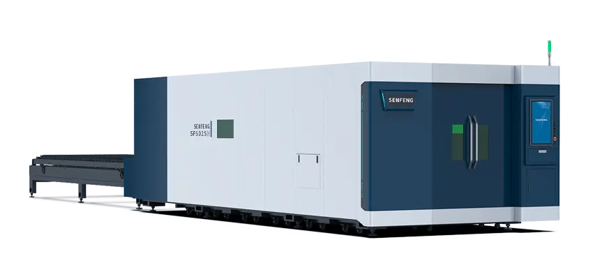
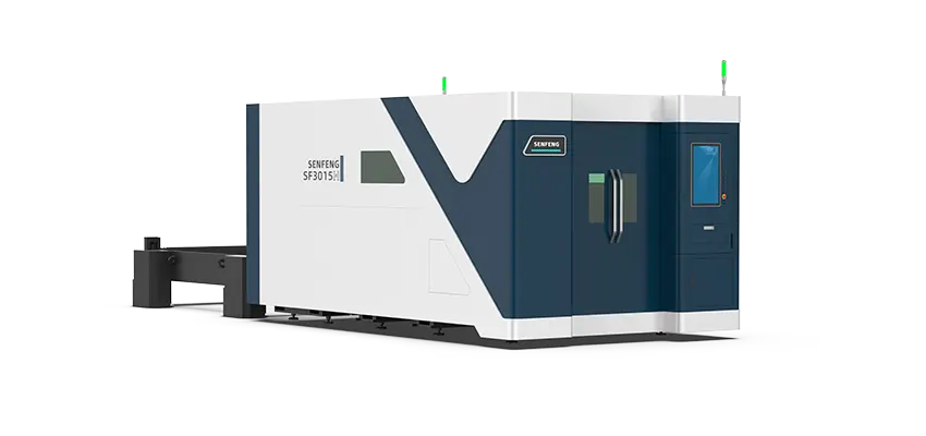
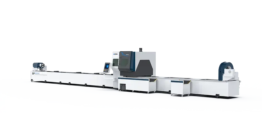
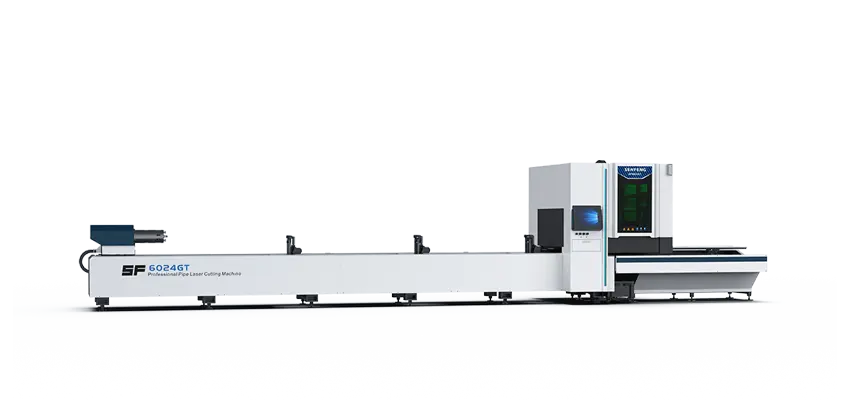
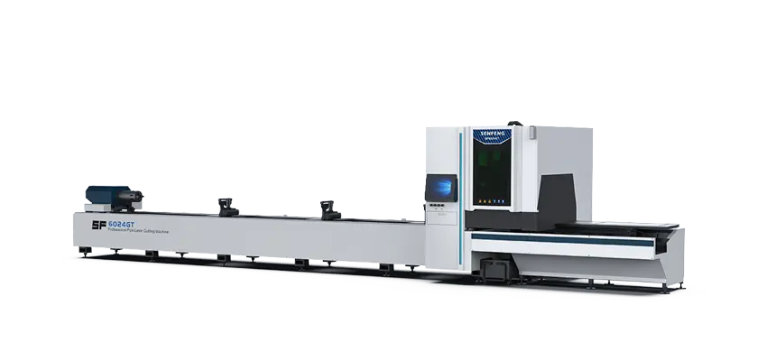
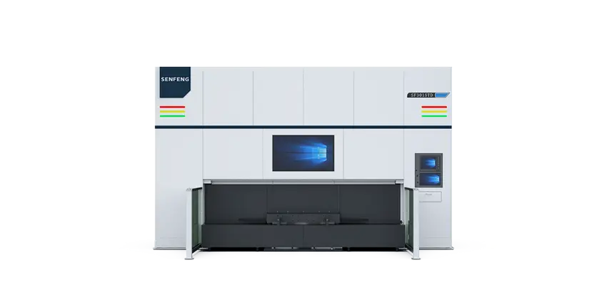
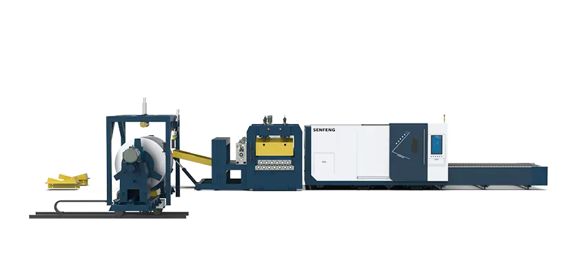
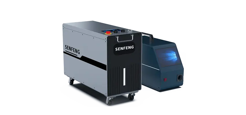
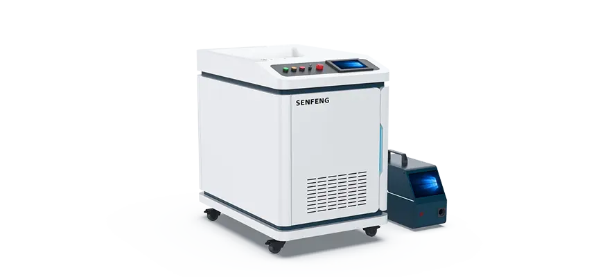
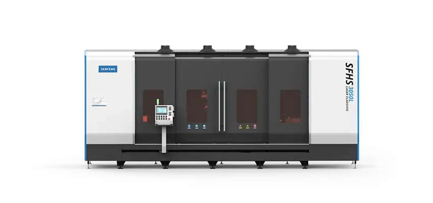
Modern laser system such as those developed by SENFENG are designed to reduce these variables through stable beam delivery, standardized process libraries, and intelligent cutting parameter management.
In real manufacturing environments, this is what ultimately determines whether production remains stable–or becomes constantly adjusted.
For more practical maintenance demonstrations and on-site troubleshooting cases, you can refer to SENFENG’s after-sales support channel: